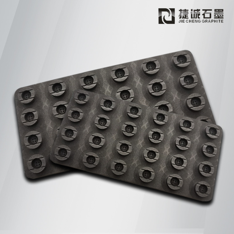
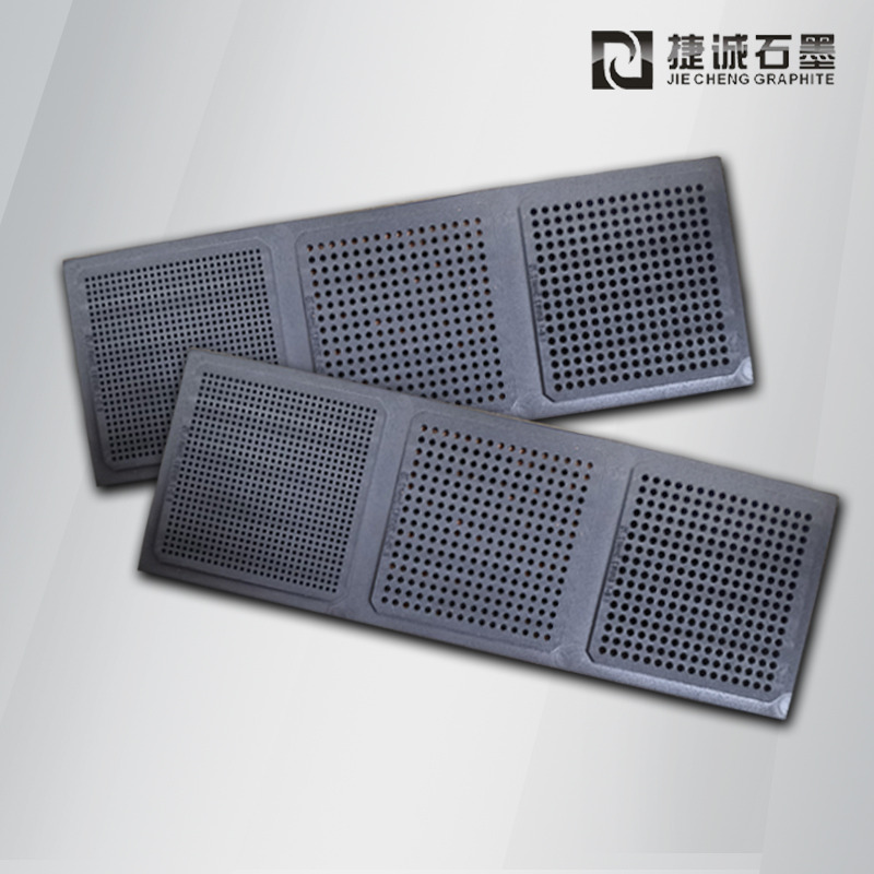
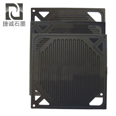
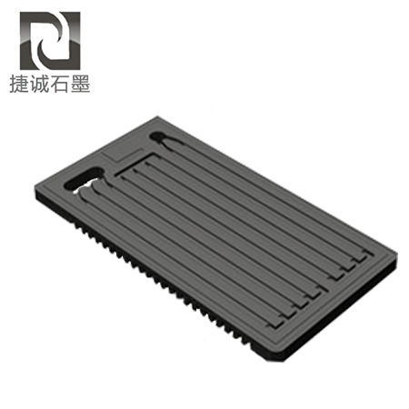
Graphite sintering molds for the electronic ceramics industry serve mass production of components such as MLCCs, varistors, piezoelectric ceramics, and thermistors, and involve complex array cavities, venting grooves, and locating structures. Many customers place orders specifying only overall dimensions, with key technical requirements communicated verbally and never documented on the drawing. The machining supplier then produces according to generic graphite processes, and after going online problems emerge—carbon contamination, mold sticking, cavity dimension drift, thermal-cycle cracking—delaying production scheduling and causing batch scrapping of ceramic green parts. A well-specified machining drawing must clearly annotate the following parameters.
I. Graphite Substrate Specifications: Lock Down Purity and Basic Physical Properties
Graphite forming method and grain specification. Clearly state whether the graphite is isostatic, molded, or extruded, and specify the target grain size. For high-cleanliness applications such as MLCCs and piezoelectric ceramics, ultra-fine-grain isostatic graphite should be uniformly required; for low-requirement products such as magnetic materials, medium-grain molded graphite may be used. Without this restriction, suppliers can easily substitute low-cost coarse-grain billet material, whose larger porosity significantly raises the risk of material infiltration and powder shedding.
Density, ash content, and harmful element control values. Specify the nominal density of the graphite; high-density substrates offer higher creep resistance and strength and are suitable for hot-press sintering. Ash content is the cleanliness threshold—for high-end electronic components, an upper limit on total ash should be specified, together with limits on alkali metal impurities such as iron, sodium, and potassium. A note may be added requiring supporting ICP test reports to avoid color differences and electrical performance drift caused by impurity precipitation at high temperature.
Operating condition notes. Add notes on the drawing stating the sintering atmosphere, maximum working temperature, and whether hot pressing is involved. Vacuum/inert atmosphere, air, and hydrogen atmospheres each require completely different modification schemes. Without operating condition notes, the supplier will default to bare graphite machining, which will rapidly oxidize and fail through material infiltration in furnaces containing volatiles or trace oxygen.
II. Cavity, Locating, and Structural Dimension Tolerances: Match Sintering Shrinkage
Cavity dimensions, depth, and sintering shrinkage allowance. Ceramic green parts shrink during sintering, so cavity dimensions cannot be equated directly with finished component dimensions; the drawing must specify the reserved shrinkage compensation. For multi-cavity array molds, strictly specify the depth tolerance of each cavity to ensure every cavity has a consistent height and uniform heating and pressure; wall thickness and base plate thickness must be specified separately—too thin a wall is prone to thermal-shock cracking, while too thick a wall causes uneven heat accumulation.
Locating structure position tolerances and fit clearances. Position tolerances must be specified for locating pin holes, locating shoulders, and alignment datums, along with the fit clearance between pins and holes. Excessive clearance causes green body misalignment and inconsistent sealing edge width; insufficient clearance causes jamming from thermal expansion at high temperature and tearing of ceramic parts during removal. For matched upper and lower mold sets, the parallelism requirement after pairing must also be specified.
Fillet and venting/flow-guide structure parameters. Specify R fillets for all cavity internal corners and step corners to eliminate stress concentration and reduce the probability of cracking under thermal cycling. For formulations with large binder burnout volumes, the drawing should indicate the position, depth, and width of vent holes and flow-guide grooves, with hole walls required to be smooth and burr-free; missing or incorrectly dimensioned venting structures lead to poor burnout and bubbling/delamination of the green body.
III. Finish Machining and Surface Modification Requirements: Control Mold Sticking and Contamination
Working surface roughness and grinding area designation. For cavity surfaces that come into direct contact with powder green bodies, specify that grinding is required and give the Ra value; non-mating outer walls may remain milled to balance machining costs. Milling without grinding leaves tool-mark grooves that trap carbon powder and volatiles, forming stubborn deposits over repeated sintering that scratch the green body and cause black-spot defects.
Surface modification type and application area. Clearly state whether vacuum resin impregnation anti-infiltration or CVD-SiC coating is used, and specify the modification scope: cavity working surfaces only, or the entire part. Also note whether secondary precision grinding is required after coating; coating adds thickness, and without re-grinding it creates height differences in the cavity and uneven pressure distribution. For high-purity sample molds that require no modification, the drawing must also note that coating and impregnation are prohibited.
Edge protection requirements. Specify edge chamfers or small fillets. Graphite is highly brittle, and sharp edges and corners chip easily during transfer and furnace loading; detached graphite fragments falling on the green body surface directly cause carbon black-spot scrapping.
IV. Post-Processing, Inspection, and Delivery Agreements: Reduce Later Disputes
High-temperature purification roasting requirements. For molds used with high-purity electronic ceramics, the drawing should note an inert-atmosphere high-temperature impurity removal process to eliminate cutting oil and ultra-fine carbon powder embedded in micropores. Without this process specified, the manufacturer will only perform simple air blowing for dust removal, and residual impurities will volatilize and precipitate during the first temperature rise, causing batch discoloration defects.
Factory inspection items. Specify the items to be tested: CMM dimensional sampling inspection, visual inspection for appearance cracks, and density sampling inspection; for thin-walled, multi-groove complex molds, non-destructive testing requirements may be added to detect hidden microcracks produced during machining and avoid sudden fracture under high-temperature pressing.
Packaging and storage requirements. High-purity molds should be individually sealed in dust-proof packaging and stored separately from ordinary graphite workpieces to prevent cross-contamination by dust and oil during storage and transport.
The drawing is the carrier through which both supplier and buyer unify process standards; verbal agreements easily lead to misunderstandings. Electronic sintering is a continuous mass-production process—once a large batch of molds has been machined and only then found to have non-conforming parameters, repair cycles are long and replacement costs are high. Only by putting material, tolerance, structure, surface treatment, and purification requirements all onto the drawing can on-line risks be avoided at the source and production line yield stabilized.