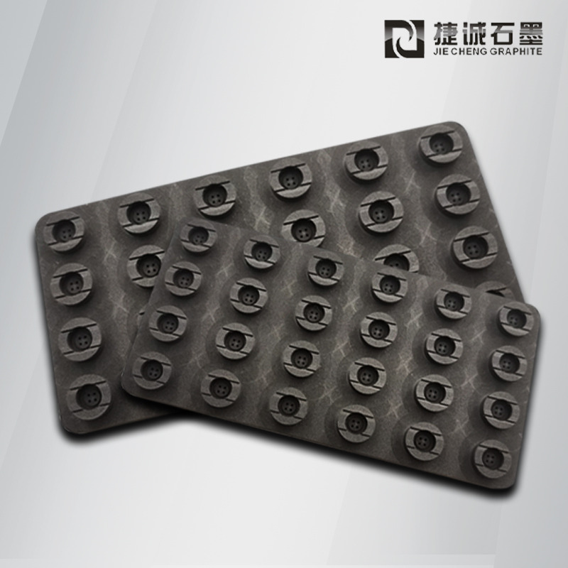
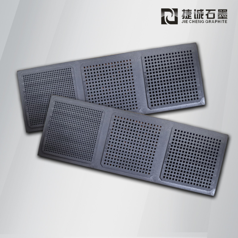
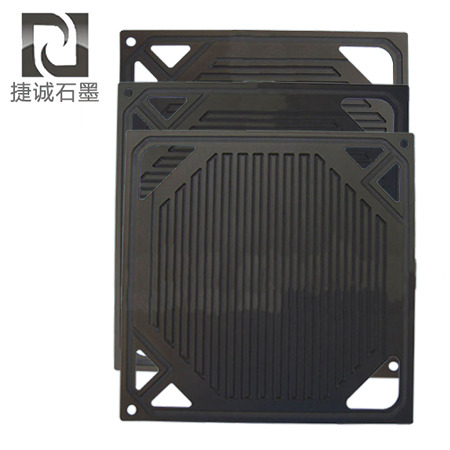
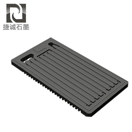
The sintering of electronic ceramic components such as MLCCs, varistors, piezoelectric ceramics, and thermistors imposes stringent requirements on temperature uniformity, cleanliness, and dimensional consistency. Metal molds are prone to deformation at high temperatures and to reacting with the green bodies. Graphite molds, with their advantages of low thermal expansion, uniform thermal conduction, and chemical inertness, have become the mainstream high-temperature tooling. In many production lines, yield fluctuations do not stem from powder formulations or sintering curves, but rather from the fact that the graphite mold's substrate, machining, and modification scheme do not match the process conditions.
I. Substrate Selection: Purity, Particle Size, and Porosity Are the First Line of Defense
Prioritize ultra-fine-grain isostatic graphite. Electronic ceramic components are highly susceptible to impurities; therefore, fine-grain isostatic graphite with a grain size within 5 μm should be preferred, with ash content controlled below 50 ppm. ICP test reports can be provided to control harmful alkali metal elements such as sodium, potassium, and iron. The isotropic grain structure results in small differences in thermal expansion in different directions under thermal cycling, making the mold less prone to warping and deformation during repeated sintering. Ordinary molded or extruded graphite has coarse porosity and is only suitable for sintering low-value-added magnetic materials.
Balance density, strength, and venting performance. High-density graphite offers high compressive strength and is resistant to creep collapse under hot-pressing conditions; however, excessively low porosity hinders the discharge of binder volatiles during the binder burnout stage, causing bubbling and delamination of the green body. For MLCC tape-cast green parts with large burnout volumes, an appropriate level of fine, interconnected porosity must be retained to balance venting and anti-infiltration capability—one should not blindly pursue ultra-high density.
Unify the billet grade and batch across the same production line. Graphite from different manufacturers and different batches varies in impurity composition, porosity, and coefficient of thermal expansion. Mixing old and new molds in use leads to unstable concentrations of volatile impurities in the furnace chamber, making components from the same batch prone to color differences and parameter dispersion. For mass-production lines, it is recommended to fix a single grade and rotate molds into service in batches.
II. Precision Machining: Cavity Accuracy and Venting Structure Determine Product Consistency
Cavity tolerances must match the sintering shrinkage of ceramics. Electronic ceramics exhibit sintering shrinkage of 15%–25%, so cavity dimensions cannot be machined directly to the finished product dimensions; shrinkage allowance must be reserved in advance. For multi-cavity array molds, depth of cavities and positional tolerances of holes must be strictly controlled to ensure that every component in a single furnace run experiences identical pressure and thermal conditions, avoiding dimensional yield divergence. Cavity corners should be uniformly rounded with an R fillet to eliminate stress concentration and reduce thermal-shock cracking.
Grind the working surface to reduce the risk of powder entrapment and mold sticking. Pure CNC milling leaves residual tool marks and grooves; these grooves trap carbon powder and powder volatiles, which form hard deposits after high-temperature exposure, scratching the green parts and producing carbon black spots. Working surfaces that come into direct contact with ceramic green bodies must be ground after finish machining to reduce surface roughness. Locating pins and locating slots should have a reasonable fit clearance; excessive clearance causes component misalignment, while thermal expansion at high temperature can cause jamming and tearing of the sealing edge.
Arrange venting and flow-guide structures as required. Binder burnout is a critical step in electronic ceramic sintering. Based on the volatile content of the green body formulation, vent holes and flow-guide grooves should be designed to ensure smooth discharge of organic gases. Hole walls must be smooth and free of burrs to prevent volatiles from adhering and accumulating, which could block the channels within a short period and shorten mold service life. For thin-walled, shallow-cavity molds, PCD diamond tooling should be used, with rough and finish machining separated to release cutting stresses and avoid internal microcracks that are invisible to the naked eye.
III. Surface Modification and Operation & Maintenance Control: Delay Mold Failure and Reduce Defects
Match the modification scheme to the sintering temperature. For mid-to-low-temperature MLCC and thermistor sintering below 1000°C, vacuum impregnation anti-infiltration treatment should be used to seal surface micropores and block the infiltration of binders and alkali metal vapors into the substrate. For high-temperature piezoelectric ceramic sintering above 1200°C, CVD-SiC coating should be used for oxidation resistance and resistance to vapor-phase erosion; after coating, secondary grinding is performed to eliminate temperature-induced color differences caused by uneven coating thickness. For R&D trial samples in high-purity vacuum or inert atmospheres, uncoated bare graphite may be used to avoid the introduction of impurities by the modification layer.
Perform a high-temperature purification process before putting new molds into production. Ultra-fine carbon powder and cutting oil embedded during cutting and grinding cannot be removed by simple air blowing. For molds supporting high-purity electronic ceramics, after machining is completed, they should be roasted in an inert atmosphere to remove impurities, releasing volatile impurities in advance to avoid black-spot defects in the entire first batch. Dust-proof isolation must be maintained throughout machining and transfer; processing should be separated from ordinary graphite products to prevent cross-contamination by dust.
Establish inspection and scrapping criteria. After each furnace run, check the working surface for carbon buildup, coating peeling, edge chipping, and microcracks. If material infiltration, looseness, or powder shedding occurs, the mold should be taken offline for repair or scrapped promptly. Control heating and cooling rates and cool slowly to reduce thermal shock; for uncoated graphite molds, strictly control the oxygen content in the furnace to inhibit oxidative powdering and shedding.
Graphite sintering molds for electronics are a key to yield hidden within the sintering process. Choosing low-priced, coarse-grain graphite molds based on price alone saves procurement costs in the short term, but the resulting component scrap and downtime for debugging will multiply the losses. Customizing the substrate, machining, and modification scheme according to sintering temperature, atmosphere, and powder formulation—and incorporating molds into routine tooling inspection—is the way to stabilize batch yield and reduce unnecessary losses.